


Please Leave Us A Message
Privacy statement: Your privacy is very important to Us. Our company promises not to disclose your personal information to any external company with out your explicit permission.
 September 19, 2019
Abstract : The TC80310 is a automotive-specific monolithic Alternator Voltage Regulator integrated circuit (IC) from Freescale Semiconductor. Compared to previous regulator products, the load response control (LRC) function is retained, specifically integrating the local interconnect network (LIN). The vehicle engine control unit (the ECU can control the output voltage of the generator by adjusting the excitation current and the LRC rate through LIN. The unique self-starting operation mode enables the motor to be used as a start-up generator and is applied to the vehicle start-stop system.
This article refers to the address: http://
In the process of using the car, the speed of the car is often unstable due to the influence of external factors and internal parameters, which affects the running quality of the car. In severe cases, it will have adverse consequences. To this end, an Alternator Regulator should be installed in the vehicle's power supply line to improve and eliminate the above phenomenon. The TC80310 is a monolithic alternator voltage regulator integrated circuit (IC). Integrates with the Local Interconnect Network (LIN) to provide enhanced control for automotive alternators. Alternator manufacturers can use the IC programmable feature to control battery regulation voltages to optimize overall performance and battery life throughout the life of the vehicle. The unique self-starting mode allows the motor to be used as a start-up generator for the vehicle start-stop system.
1 chip introduction
The 80310 pin function and peripheral circuit are shown in Figure 1.
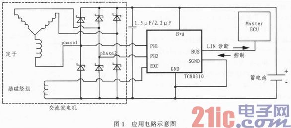
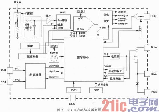
The internal structure is shown in Figure 2. The 80310 is powered by the B+A pin. This voltage is also the feedback voltage of the control circuit. VP1 and VP2 are derived from the PH1 and PH2 phase signals, respectively. The difference between the two signal voltages is the phase voltage, which is effective when the phase voltage is greater than 0.45V. When VP1>8V and VP2<1V, an internal pulse signal P1_AND_P2 (CLK Phase) is generated, which can reflect the current phase frequency. The IC supplies current to the excitation coil of the alternator through the high side of the MOSFET. A freewheeling diode is provided inside the chip to keep the battery voltage of the car at the set value and output current (up to 8.0A) to the power device. The ADC is used for analog to digital conversion in voltage, current, and thermal feedback. The purpose of the POR (Power On Reset) module is to generate an electrical start signal to the main logic. The energy gap module supplies voltage and current to other modules. The IC can be programmed by OTP (One Time Programmable) (one-time write at the factory) to accommodate a variety of generators and devices.
The 80310 has an industrial grade LIN protocol interface (version 1.3). This allows the ECU to adjust the generator's target voltage (10.6 to 16V), LRC ramp time, LRC disable frequency, and excitation current limit. The ECU can also read Die temperature, field current, EXC duty cycle (DF), product information and various error messages via LIN. Once the LRC disable frequency is achieved, the charging system will provide a faster response. When the engine is at low speed, an increase in sudden electrical load demand can result in a sudden torque load, and the LRC eliminates the resulting engine rate oscillations and vibrations.
2 working mode
2.1 LIN mode
While waiting for the state, the Master can wake up the 80310 via the LIN transmit control signal without entering a valid phase voltage. The slave can enter LIN mode (the slave address is #39 or #2B). The working state is shown in Figure 3.
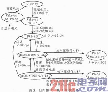
When the 80310 Diagnostics Master command is valid (the generator target voltage is not equal to 10.6 V and there is no error signal), the pre-excitation state is entered. At this time, if the voltage of B+A is lower than the target voltage, the pre-excitation is a PWM with a duty ratio of 13.5%, otherwise the duty ratio is 4.1%. The purpose of pre-excitation is to enhance the magnetization of the generator to ensure the minimum phase voltage of the generator rotor when the engine is started. When the phase velocity reaches 800 RPM, enter the LRC control.
Under the LRC control, the duty ratio of the 80310 control excitation is gradually increased, and the output voltage of the generator is adjusted to the set voltage. At this time, the phase frequency and output voltage increase as the excitation increases. When the phase frequency reaches 2400 RPM and the output voltage reaches the target voltage, it enters the LRC-free regulation control. At this time, the duty ratio of the 80310 control excitation is constant, and the output voltage is stable. If the phase frequency is below 2400 RPM, the 80310 returns to LRC mode. If the phase frequency is below 500 RPM, exit the LRC control and enter the pre-excitation mode.
In the LRC and no LRC control cycle, if the phase voltage is lower than 8 V in the previous cycle, the repetitive regulation mode is entered until the high phase voltage appears. At this time, the excitation duty ratio is 100%. At the end of the eighth cycle, if the high phase voltage has not yet occurred, it returns to the previous state.
If there is no LIN control signal on the bus for more than 3 s, it will automatically enter the self-starting mode.
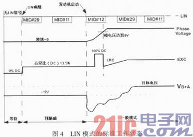
The schematic diagram of phase voltage, excitation and battery voltage in the standard operating state of LIN mode is shown in Figure 4.
2.2 Self-start mode
In the wait state, the valid phase voltage is detected instead of the LIN signal, then the 80310 is woken up into the self-start mode. The excitation of the phase frequency is greater than 3 000 rpm within 100 ms of wake-up, and the 80310 provides excitation with a duty cycle of 100%. Otherwise, it returns to the wait state and waits for the next wakeup. If 100% of the excitation causes the motor to start within 100 ms, it enters the pre-excitation state, and the subsequent working state is the same as the LIN mode. The target voltage defaults to 13.8 V. If the motor fails to start, it returns to the wait state and waits for it to wake up.
In this mode, the chip provides 100% excitation, allowing the motor to self-start. By changing the direction of the current in the motor control circuit, the motor can be switched directly between the generator and the motor. In this way, the motor can be used as a starter generator. In the self-start mode, once a valid LIN control signal is detected, it enters LIN mode. If there is no LIN control signal within 3 s, it will work according to the self-start mode again.
For light cars, the self-starting mode can basically meet the requirements of the motor during normal starting and driving. But when the energy is fed back, the motor works in the power generation mode and requires a larger torque to recover the energy. At this time, the LIN mode can quickly help the energy recovery.
2.3 Other working modes
When the battery output voltage is 10.6 ~ 16 V, the 80310 operates in normal mode (LIN mode and self-start mode). Above 16 V, the 80310 gives excitation with a minimum PWM duty cycle (4.1%). Overvoltage error detection at voltages greater than 16.5 V. Overload protection greater than 21 V, excitation off. When less than 10.6 V, the maximum excitation is given. Below 5.0 V, logic reset.
3 Typical applications
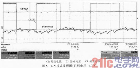
The 80310 is suitable for 6-phase brushless DC Motors. According to the application circuit to set up the experimental environment, the LIN mode and the self-start mode are tested separately. Figure 5 shows the waveform when the target voltage is set to 14.7 V in LIN mode and the system reaches a steady state, that is, without LRC adjustment. At this time, the voltage of B+A is approximately equal to the target voltage of 14.7 V, and the excitation duty ratio is stabilized at 44.4%.
4 Conclusion
The TC80310 has a single-line LIN connection with the ECU to improve the controllability of the motor, stabilize the battery voltage, and make the system more secure.
The above is the Car LIN Control Alternator Regulator TC80310 we have listed for you. You can submit the following form to obtain more industry information we provide for you.
You can visit our website or contact us, and we will provide the latest consultation and solutions
Send Inquiry
Most Popular
lastest New
Related Products
Send Inquiry
Privacy statement: Your privacy is very important to Us. Our company promises not to disclose your personal information to any external company with out your explicit permission.
Fill in more information so that we can get in touch with you faster
Privacy statement: Your privacy is very important to Us. Our company promises not to disclose your personal information to any external company with out your explicit permission.