


Please Leave Us A Message
Privacy statement: Your privacy is very important to Us. Our company promises not to disclose your personal information to any external company with out your explicit permission.
 May 17, 2019
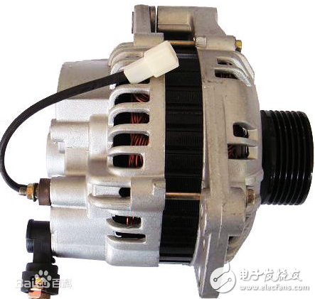
An automotive generator is the main power source of an automobile. Its function is to supply power to all electrical equipment (except starters) while the engine is operating normally (idle speed) and to charge the battery at the same time.
On the basis of the three-phase stator windings of the common alternator, the number of winding turns is increased and the terminals are led out, and a three-phase bridge rectifier is added. When the speed is low, the primary winding and the increased winding are output in series, but at a higher speed, only the original three-phase winding is output.
The alternator for automobiles mainly consists of a rotor, a stator, a rectifier, and front and rear end covers. As shown in Figure 2-1.
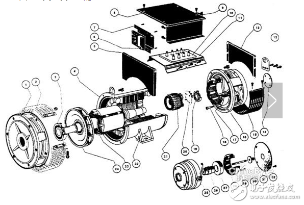
Figure 2-1 The composition of the alternator
1. Rotor
The function of the rotor is to generate a magnetic field. The rotor is mainly composed of rotor core, excitation coil (also called magnetic field coil), claw pole and slip ring, as shown in Figure 2-2.
Two claw poles are mounted on the rotor shaft, and a rotor core and an excitation coil are installed in the cavity between the claw poles. The excitation coil is wound on the iron core, and the iron core is press-fitted on the rotor shaft between the two claw poles. The slip ring consists of two copper rings insulated from each other, press-fitted at one end of the rotor shaft and insulated from the rotor shaft. The two ends of the excitation coil lead out from the two small holes on the inner claw pole, one end is welded on the inner copper ring of the slip ring, and the other end is threaded through the small hole on the inner copper ring and welded on the outer copper ring. The two copper rings are in contact with the two brushes of the generator, respectively. When the two brushes are connected to the DC power source, a current flows in the excitation coil and an axial magnetic flux is generated, so that one claw pole is magnetized as an N pole and the other claw pole is magnetized as an S pole, thereby forming six pairs. Interlaced magnetic poles.
The purpose of designing the rotor claw pole as a bird's beak type is to make the magnetic field sinusoidally distributed, and the induced electromotive force generated by the armature coil approximates a sinusoidal waveform.
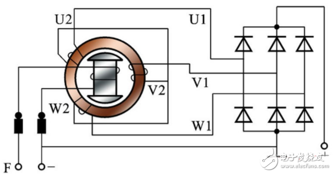
Figure 2-3 The composition of the stator
2. stator
The function of the stator is to generate alternating current. Its structure is shown in Figure 2-3. It is composed of a stator core and a stator coil. The stator core is made up of annular silicon steel plates with inner grooves, and the silicon steel plates are insulated from each other. The stator coil is a three-phase symmetrical coil and is installed in the slot of the stator core. The connection method of the three-phase coils adopts a star connection, each of the three-phase coils leads one terminal, and the neutral point leads to one terminal.
3. Rectifier
The alternator rectifier consists of six silicon diodes. The lead of the diode is a pole of the diode, and its housing part is the other pole of the diode. The shells of the three silicon diodes press-fitted on the rear end cover (or grounding heat sink connected to the housing) are diode anodes, and the cathode of which is the diode cathode, which is called the cathode tube; press-fitted on the insulating radiator plate of the housing. The shell of the three silicon diodes is a negative electrode, and the lead terminal is a positive electrode of a diode, which is called a positive electrode tube. The lead terminals of the three positive tubes and the three negative tubes are connected in a one-to-one correspondence through three terminals, and are respectively connected to the A, B, and C terminals of the three-phase coils to form a three-phase full-wave rectifier circuit.
A bolt fixed to the radiator plate protrudes outside the generator housing and serves as an output terminal of the generator.
The terminal is the positive pole of the generator and the corresponding symbol is "B" (or "+" or "armature", etc.).
4. End cap and brush assembly
The front and rear ends of the alternator are cast from aluminum alloy. The aluminum alloy is a non-magnetic material, which can reduce magnetic leakage, and has the advantages of light weight and good heat dissipation.
A brush assembly and a regulator assembly are mounted on the rear end cover. The brush assembly consists of a brush, a brush holder and a brush spring. The brush is mounted in the hole of the brush holder, and the brush maintains good contact with the slip ring by spring tension. Each brush has a lead that leads directly into the IC regulator and connects the excitation coil to the regulator's operating circuit.
A fan and a V-belt pulley are installed in front of the front cover of the generator, and the engine drives the generator pulley and the rotor through the V-shaped belt. The ventilation of the generator depends on the fan. Ventilation openings are made on the front and rear end covers. When the fan rotates with the pulleys, air flows from the air inlets and flows out of the air outlets through the generator. This brings out the internal heat of the generator. To achieve the purpose of cooling.
Rectifier circuit working principle
Altering the alternating current generated by an alternator to direct current is called rectification. The common rectification circuit is a rectification circuit of a six-tube alternator and a rectification circuit of a nine-tube alternator.
1) Rectifier circuit for six-tube alternator
The rectifying device of a six-tube alternator is actually a three-phase bridge rectifier circuit composed of six silicon rectifier diodes (see figure). The cathodes of the three diodes VD2, VD4 and VD6 are respectively connected to the beginning of the three-phase winding of the generator, and their positive electrodes are connected together to form a common anode connection. The conduction principle of the three diodes is that the negative potential is the lowest at a certain instant. The diode turns on. The positive poles of the three diodes VD1, VD3 and VD5 are respectively connected to the beginning of the three-phase winding of the generator, and their cathodes are connected together to form a common cathode group connection method. The conduction principle of the three diodes is that the potential of the cathode is at the highest moment. The diodes conduct preferentially. Two diodes are turned on at the same time. One diode is in the common cathode group and the other is in the common anode group. The two tubes that conduct at the same time always add the generator voltage across the load, as shown in the figure below. Show.
When t=0, the potential of the C phase is the highest, and the potential of the B phase is the lowest, and the corresponding diodes VD5 and VD4 are all in forward conduction. Since the internal resistance of the diode is small, the output voltage of the generator at this time is equal to the line voltage between the B and C windings.
During the period from t1 to t2, the potential of phase A is the highest and that of phase B is the lowest, so the corresponding VD1 and VD4 are in the forward conduction. Similarly, the output voltage of the AC engine can be regarded as the line voltage between the A and B windings.
During period t2-t3, phase A has the highest potential and phase C has the lowest potential. Therefore, VD1 and VD6 are in forward conduction. Similarly, the output voltage of the AC engine can be regarded as the line voltage between the A and C windings.
By analogy, over and over again, a relatively smooth DC ripple voltage can be obtained on the load.
2) Rectification of Nine-tube Alternators
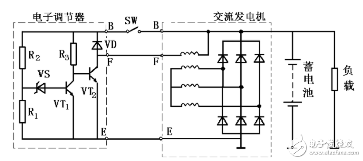
The characteristic of the nine-tube alternator is that in addition to the commonly used six rectifier diodes, three more low-power diodes have been added. Three lower power diodes are used to supply the alternator field current, which is also known as a magnetic field diode. After using the magnetic field diode, the output terminal is connected with the charging indicator lamp to indicate the working condition of the generator. The circuit of the nine-tube alternator charging system is shown in Figure 3.
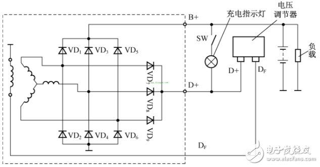
Fig. 3 Circuit diagram of nine-tube alternator charging system
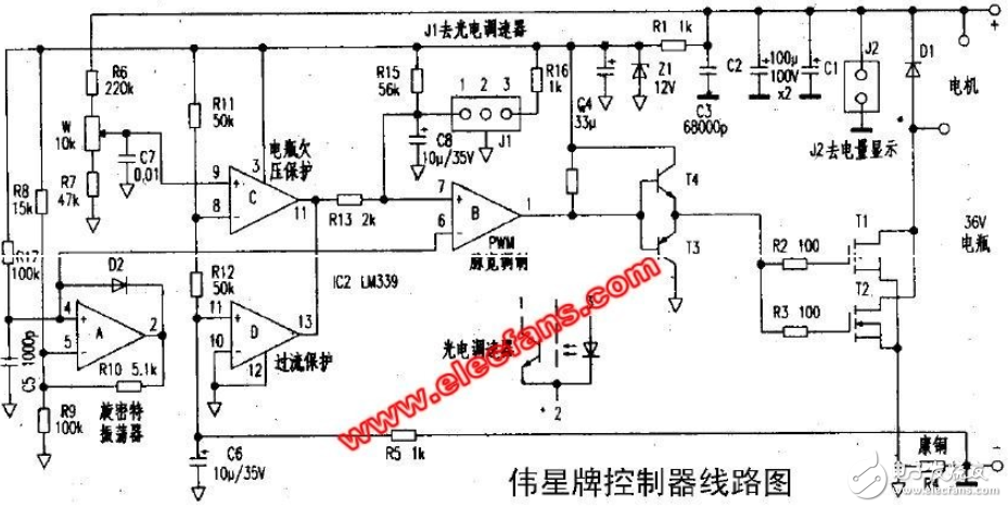
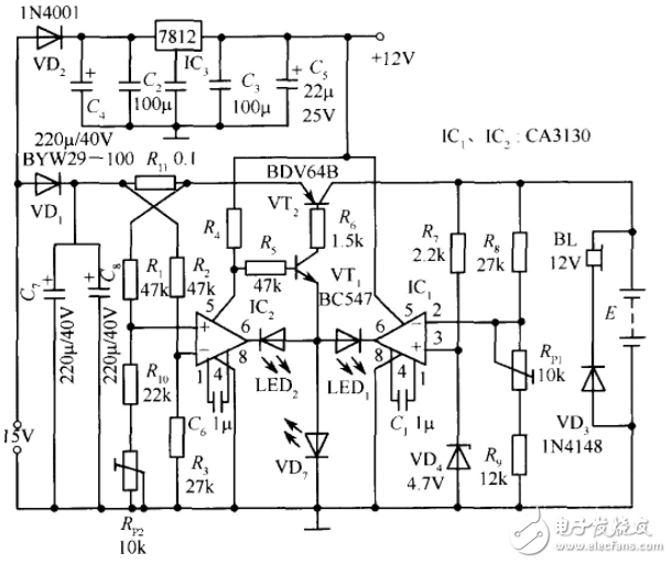
Motor generator charging circuit (2)Electric vehicle 36V battery charger circuit diagram
Car Battery Charger Circuit Diagram
The above is the Auto Generator Charger Circuit Encyclopedia (Six-tube Alternator/Nine-tube Alternator/Charger) we have listed for you. You can submit the following form to obtain more industry information we provide for you.
You can visit our website or contact us, and we will provide the latest consultation and solutions
Send Inquiry
Most Popular
lastest New
Send Inquiry
Privacy statement: Your privacy is very important to Us. Our company promises not to disclose your personal information to any external company with out your explicit permission.
Fill in more information so that we can get in touch with you faster
Privacy statement: Your privacy is very important to Us. Our company promises not to disclose your personal information to any external company with out your explicit permission.